
Address all questions and comments to TheLaughMakers@GMail.com and I'll be happy to answer them.
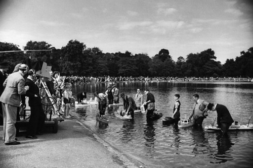

| Pond Racing, Clapham, England, 1936 |
| Main deck and brass fittings on a 1930s pond boat |
| Vintage solid hull pond yacht, circa 1935 |
 |
| Two-masted swimming pool yacht, circa 2016 |
 |
| Bowsprit of the schooner Hope in drydock |
 |
| Poop Deck on the Hope |
 |
| Deck House on the Hope |
Many hobbiests build pond boats just to admire the beauty of them. These are museum quality models meant for display rather than to be pressed into service on the high seas. Most, however, are completely seaworthy as well as handsome.

| Scale model of America's Cup J Yacht Ranger built in 1936 |
| The Northern Crown built by Rob Eddy of Camden, Maine |
CONSTRUCTING THE HULL
The two most popular and most often used methods of constructing a wooden pond boat are plank-on-frame -- which most closely resembles how real boats are made -- and bread and butter which requires sculpting the hull out of layers of knot free wood, usually pine, glued together. Here are some illustrations of plank-on-frame construction:
Here are some examples of solid hull, bread and butter construction -- the process I used to construct the Hope, the Courage, and the Dream shown in my pool at home and the easier, in my opinion, of the two methods:
As you can see, the boards are cut to shape, glued together, and then sculpted with the tools shown. Notice there is no saw included. I prefer to form a rough outline of the hull's outer surface by sawing the pieces as they're glued to one another, rather than chiseling and planeing them into submission after all the layers (decks) have been joined together. I don't know about you, but I find a saw much easier to control than a chisel as the tendency to gouge the wood too deeply is always lurking in the background:
KIT BUILDING vs. SCRATCH BUILDING
My first attempt at making a model ship was a plank-on-frame kit from a company called Artasania Latina, a two-masted schooner named the Harvey. I found the hobby relaxing and a welcome respite from my regular job as a TV writer. It helped to have a separate room in which to complete the project. The model remained at the ready anytime I felt like working on it. It was just a matter of following the plans, step-by-step. All parts are provided so nothing needed to be purchased separately. And there was no painting involved as I decided to keep the natural wood as is, finished only with a coating of Swedish wood oil.
 |
| The Harvey |
My next model, from the same kit maker, was the famous Boston whaler -- which is docked in Mystic Seaport, CN -- the Charles W. Morgan. This model was a little larger and more complex, but required basically the same process. Again, no painting was needed, just a coating of oil to bring out the natural wood colors. The Morgan was launched in 1841, the last in the U.S. whaling fleet and was decommissioned in 1921.
 |
| The Charles W. Morgan |
I built my first scatch boat from a single block of clear pine I had commandeered from a scrap heap at a nearby building site. Using a small saw, I shaped the wood roughly, then finished the scupting with a wood plane. After sanding all the surfaces smooth, I painted it with acrilic paint from a hobby store. There aren't many complex curves on a cruise ship so it was an easy way to ease into creating pool boats that actually had to float. Therein would lie the challenge.

 |
| Deck Cabin on the Courage |

Next, I drew the outline of the sailboat I had in my head. It would be extra long in relation to its beam (the width of the main deck, starboard to port). I figured sawing would be easy since I'd never have to saw very much wood away at one time.
Note that the first cut is at a severe angle and it's the second cut that softens the curve. Planeing and sanding would complete the process of achieving smooth, gently rounded curves exactly where you want them.
I formed the bow and the stern first, outlining them on the main deck. I cut at sharp angles which would be rounded out with more cuts later. By sawing small increments at a time, an almost round edge can be achieved and planed into a smooth curve later.

Note that the first cuts are sawed at right angles to the surface. The inward curves from the gunwales to the keel are cut later.


 |
| The Courage during ballast testing |

Using examples I saw online, I knew I'd need a keel, but decided to add it later rather than including it as part of the hull which some of the examples on line did. This would be cut from a piece of 1/2 in. pine and secured to the hull with wood screws. The keel provides ballast to keep the boat from capsizing. Weight is added during actual ballast testing in the water. Note that in the first photo above, the keel is shaped differently than the one my initial drawing. I found that, because of the model's narrow beam, she would need a much deeper keel. Note the lead sinkers (purchased at the fishing section of Big 5) wired to the platform at the very bottom.

The Dream
Before completing the Courage, I had already decided that my second pond boat would have a wider beam and thus be more stable in the water, as the Courage (with its narrow beam) was not. As a general rule of thumb, the wider the beam a boat has the less ballast it will need below the waterline to equalize the center of gravity and keep the vessel "on an even keel." While ballast testing the Courage, I discovered she needed a lengthy keel that would be twice as long as the depth of her hull from upper deck to false keel. So this time, using the same 1 1/2" x 2 1/2" pine used for the Courage, I arranged five 24 inch lengths so that the upper deck would be the width of two pieces laid horizontally, and the lower decks would narrow with the boards laid virtically beneath them. Here's how the configuration looked when glued together:


THE HOPE
For my third pond boat, the Hope, I decided to construct the hull using a more convential bread and butter process with more layers (or decks) laid horizontally. To provide a gradual downward slope from false deck to false keel, I bought 3/4" x 3 1/2" pine boards cut in 28" lengths. The upper decks would require boards glued horizontally side-by-side. I outlined the shape of the bow and the stern on the first or top deck. (Later, I would decide to add a fo'c's'le deck and a poop deck separately):

As more decks were added, their edges were planed downward and inward to provide a gradual slope toward the false keel. The bow and stern required a more pronounced slope so I used the saw to shave off layers of wood before planeing them. At the fourth layer, I began to allow for the rudder shelf (fantail) by sawing the boards straight across and rounding the corners after several layers had been glued together. To insure a stronger bond between decks, I countersunk two 1 in. screws between each layer.
When the entire outer surface of the hull had been rough sawed then planed to provide a pleasing and uniform curve from gunnels to keel, I rough sanded the entire surface, then used wood filler to cover any gaps or imperfections. After some experimentation, I found that Elmer's WoodFiller is easiest to work with, dries white, and takes either stain or paint evenly.
I painted the hulls with acrylic paint which I sealed with 10-15 coats of varnish before launching them into the pool. They should have a thick layer of varnish to protect the hulls from chlorine damage.
(illustration)


Before getting to deck planking, I cut a 1/16 in. thick false deck to cover the main deck and on which I could glue the planks. But befote I laid planks, I added a fo'c's'le and a poop deck.


Deck planking may be purchased at any hobby store and comes in many varieties from teak to maple. Pine is the cheapest and can be stained later to the desired shade.


Just to provide contrast with the main deck planking, I used popsicle sticks available at craft stores like Michael's or Hobby Lobby. Those I stained and smoothed with a power sander to achieve a different looking finish.


SELF-STEERING MECHANISM
Makers of the early pond boats back in the 1930s had to devise some sort of self-steering mechanism that would insure that their boats would return to them when the wind shifted and not sail around aimlessly. They came up with some inventive solutions, one of which involved an independent wind vane which would work independently of the sails in the event of sail damage.
Of course, swimming pool boats don't face the same risks, but you want them to respond to the shifting winds as a properly rigged sailboat would. Ideally, the rudder should react to take advantage of the wind, just it does when a human sailor is at the tiller. To devise a self-steering mechanism, the rudder must somehow be connected to the mainmast boom. On my boats, I use a common swivel such as the one that separates key rings when the plunger is squeezed.

On both the Courage and the Dream, I lashed the swivel to the tiller and attached a rod cut from a wire coathanger to the underside of the mainmast boom. I attached to the wooden tiller another wire which runs through a plastic tube-lined hole drilled in the the poop deck and connects to the rudder beneath. Note that the wire is bent forward of its entry point in this configuration.

You'll notice from the photos that the swivel on both the Courage and the Dream extended upward toward the boom rods which would pass through them. On the Hope, the swivel hangs downward.

While the steering gear configuration on the Courage and the Dream performed adequately, relocating the swivel would greatly improve it. On the Hope, I attached the swivel to the boom while the tiller itself became the rod that passed through it. Also, the swivel was placed closer to the center of the tiller's turning circumference allowing it to rotate a greater distance from port to starboard. So great a distance, in fact, a regulator was needed to keep the rudder from becoming perpendicular when turned all the way to port or starboard. The line passing through the end of the tiller effectively restricts the motion to about 150 degrees.

FITTING THE RUDDER
The rudder on all three pond boats was designed and installed in basically the same way. On the Courage, the coat hanger wire was cut so that the top end would turn into the tip of the tiller made from a piece of 1/4 in. dowel. The wire extends through a hole drilled in the fantail and is attached to the rudder externally and the connection turned inward 1/16 in. at the rudder's mid point and stapled at the end.

The Dream's rudder is different only because the rod is covered at its attachment points.

I secured the rudder on the Hope by drilling a hole near its inner edge and glueing the wire into it.

Since you've come this far, you'd best start learning a few nautical terms:

INSTALLING THE MASTS, BOOMS, GAFFS & BOWSPRIT
Now that you've sculpted a seaworthy hull, it's time to begin working on a form of locomotion man has been using since he first began his attempts to conquer the oceans. For the mests and the bowsprit, you'll need 1/2 in. dowling which will be tapered toward the ends with your plane, sanded and stained dark. The booms and gaffs will require 14 in. dowling, sanded and stained.

The mainmast should be about as tall as your yacht is long, give or take. The foremast should be a few inches shorter, but the object is to get as much sheet before the wind as you can. Masts and bowsprit should be anchored about an inch into the main deck. While the Jumbo (jib) also has a boom, it's usually narrower. For those, I've found that chopsticks sanded smooth and stained work well and they're free.
NEXT: Measuring, Cutting and Sewing the Sails
When the entire outer surface of the hull had been rough sawed then planed to provide a pleasing and uniform curve from gunnels to keel, I rough sanded the entire surface, then used wood filler to cover any gaps or imperfections. After some experimentation, I found that Elmer's WoodFiller is easiest to work with, dries white, and takes either stain or paint evenly.
I painted the hulls with acrylic paint which I sealed with 10-15 coats of varnish before launching them into the pool. They should have a thick layer of varnish to protect the hulls from chlorine damage.
(illustration)


Before getting to deck planking, I cut a 1/16 in. thick false deck to cover the main deck and on which I could glue the planks. But befote I laid planks, I added a fo'c's'le and a poop deck.


Deck planking may be purchased at any hobby store and comes in many varieties from teak to maple. Pine is the cheapest and can be stained later to the desired shade.


Just to provide contrast with the main deck planking, I used popsicle sticks available at craft stores like Michael's or Hobby Lobby. Those I stained and smoothed with a power sander to achieve a different looking finish.


SELF-STEERING MECHANISM
Makers of the early pond boats back in the 1930s had to devise some sort of self-steering mechanism that would insure that their boats would return to them when the wind shifted and not sail around aimlessly. They came up with some inventive solutions, one of which involved an independent wind vane which would work independently of the sails in the event of sail damage.
| This drawing from the 1936 is an example of wind direction finders in use at the time. Courtesy of FeyMarine.com |
Of course, swimming pool boats don't face the same risks, but you want them to respond to the shifting winds as a properly rigged sailboat would. Ideally, the rudder should react to take advantage of the wind, just it does when a human sailor is at the tiller. To devise a self-steering mechanism, the rudder must somehow be connected to the mainmast boom. On my boats, I use a common swivel such as the one that separates key rings when the plunger is squeezed.
 |
| The short brass rod on the Dream can adjust horizontally as the tiller moves under the boom toward the starboard side. |

 |
| The screw elbow was added to provide vertical mobility to the tiller attached to the mainmast on the Courage. |
On both the Courage and the Dream, I lashed the swivel to the tiller and attached a rod cut from a wire coathanger to the underside of the mainmast boom. I attached to the wooden tiller another wire which runs through a plastic tube-lined hole drilled in the the poop deck and connects to the rudder beneath. Note that the wire is bent forward of its entry point in this configuration.

You'll notice from the photos that the swivel on both the Courage and the Dream extended upward toward the boom rods which would pass through them. On the Hope, the swivel hangs downward.
 |
| Positioning the swivel closer to the center of the tiller's entrance point provided greater rudder mobility in relation to the movement of the mainmast to boom either port or starboard. |

While the steering gear configuration on the Courage and the Dream performed adequately, relocating the swivel would greatly improve it. On the Hope, I attached the swivel to the boom while the tiller itself became the rod that passed through it. Also, the swivel was placed closer to the center of the tiller's turning circumference allowing it to rotate a greater distance from port to starboard. So great a distance, in fact, a regulator was needed to keep the rudder from becoming perpendicular when turned all the way to port or starboard. The line passing through the end of the tiller effectively restricts the motion to about 150 degrees.

FITTING THE RUDDER
The rudder on all three pond boats was designed and installed in basically the same way. On the Courage, the coat hanger wire was cut so that the top end would turn into the tip of the tiller made from a piece of 1/4 in. dowel. The wire extends through a hole drilled in the fantail and is attached to the rudder externally and the connection turned inward 1/16 in. at the rudder's mid point and stapled at the end.

The Dream's rudder is different only because the rod is covered at its attachment points.

I secured the rudder on the Hope by drilling a hole near its inner edge and glueing the wire into it.

Since you've come this far, you'd best start learning a few nautical terms:
INSTALLING THE MASTS, BOOMS, GAFFS & BOWSPRIT
Now that you've sculpted a seaworthy hull, it's time to begin working on a form of locomotion man has been using since he first began his attempts to conquer the oceans. For the mests and the bowsprit, you'll need 1/2 in. dowling which will be tapered toward the ends with your plane, sanded and stained dark. The booms and gaffs will require 14 in. dowling, sanded and stained.

The mainmast should be about as tall as your yacht is long, give or take. The foremast should be a few inches shorter, but the object is to get as much sheet before the wind as you can. Masts and bowsprit should be anchored about an inch into the main deck. While the Jumbo (jib) also has a boom, it's usually narrower. For those, I've found that chopsticks sanded smooth and stained work well and they're free.
NEXT: Measuring, Cutting and Sewing the Sails